Simple electronic projects with circuit diagram
You are searching for Simple electronic projects with circuit diagram: Dear friends you will get the basic idea of how to make an electronic circuit project? How to Build a Simple Electronic Circuit? Here you will get the simple electronics mini projects circuit diagram. So let us innovate! Do you know what is AC and DC?
History behind this project
When I was a kid, then the desire or you can say curiosity to know about electronic circuits was very much inside me. I think this would happen to everyone. Every child has a desire to know something or everything.
In fact, I wanted to know about electronics, in the right way, about the electronic circuit. In the beginning, I had also created a small laboratory that was full of small components.
It was 1996 when Deepawali was celebrated and for decoration Serial bulbs ie decoration lighting for Diwali Christmas of Random Colors was used. The bulbs were connected in serial with each other to make the decorative light. We get a bulb in 50 paise, the bulbs used to come in the range of 6 volts to 12 volts those days.
Those days I have a battery of 12 volts, I used to glow those bulbs by that battery. I enjoyed working to remove the darkness of the night because gradually I started to understand myself as a small scientist.
Circuit diagram
In the initial round of Simple electronic projects with circuit diagram, I did not know about battery’s plus-minus at all. For the first time when I went to know about the LED, I came to know that there is also plus-minus in a battery, you would be laughing to hear, but then I was in Class Fifth, maybe nowadays children are smarter, they know it from the stomach-What is the plus-minus of a battery and how it works?
Yet those who do not know they should know.
There are two types of power supplies in this world. I learned it, in my childhood one is AC and the other DC.
I knew that AC gave electric socks but DC did not. Later it was discovered by me that DC gave a great shock and I was astonished. Slowly I also found that there is a phase and neutral in AC, and plus-minus in DC.
Think, when a little one makes a small circuit for the first time, even if it tries to glow a bulb and it achieves success in it, that means it will be so happy, then it will be so much happier than getting a girlfriend.
Simple led circuit diagram without Switch
So today I have brought for you how I connected a LED circuit in my childhood. How to glow an LED from a 1.5-volt battery. This is the world’s simplest circuit.
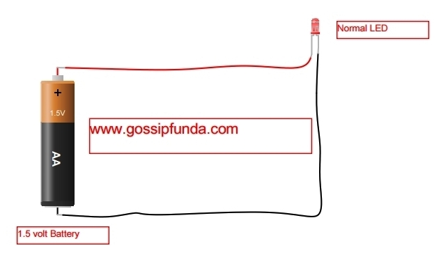
If you are looking at the electronic circuit diagram then you are getting an idea of connecting a LED by a simple battery.
Requirements:
- A 1.5-volt battery or cell
- 1.5-volt LED
- Wire
- Switch
Connection:
For the most Simple electronic projects with the circuit diagram, you need to connect the Plus Terminal of Battery/Cell to the LED Plus terminal.
Led positive and negative legs
To understand Led positive and negative legs, led symbol circuit, How to know the Plus Terminal of a LED? Read this:
LED light stands for the Light emitting diode, which means that like their diode cousins, they are polarized. To find the positive and negative pin on an LED there are some extent identifiers. You can try to find the long legs, which should indicate the positive, the anode pins.
Or, if someone has trimmed the feet, try to find the flat edge on the outer cover of the LED. The pin near the flat edge will be negative, the cathode pin. if your LED is transparent then less semiconductor material will be found on +ive Side. Hope it will be very much clear about led positive and negative legs by this diagram:

Now you have connected the +ive pins then connect the -ive pin of the LEd to the negative side of the battery. As you connect the -ive terminal circuit will be completed and LED starts to glow.
Simple led circuit diagram using Switch
if you want to connect a switch in the above circuit then cut any of the wire in the circuit where you want to add a switch. Connect the first side of the wire to the switch to another side of the wire to another terminal of the switch.
Look at this circuit diagram:
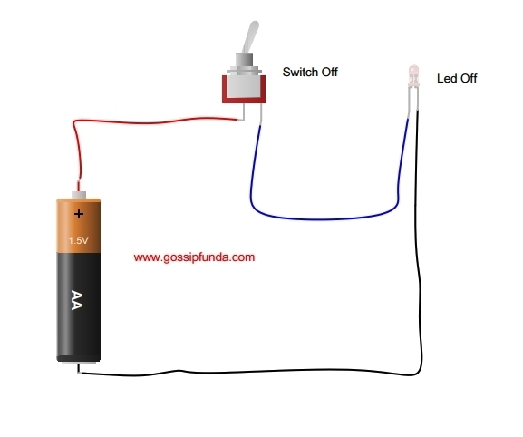
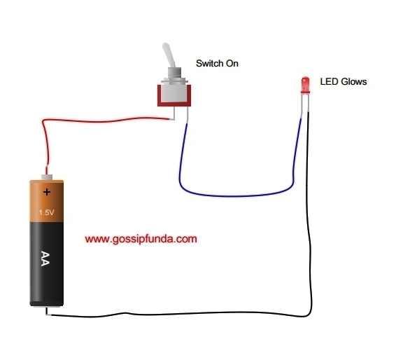
Hope you enjoyed by making this first very basic circuit. For any further circuit please visit us www.gossipfunda.com
Do not forget to put your valuable comments on Simple electronic projects with circuit diagram.
See Also:
- Resistance Color Code
- How to make perfect 5 Volt or 12 Volt Supply
- Musical Dance Light using TIP 31
- VLSI
you can also write to us at [email protected] or fill our contact form by your circuit diagrams. We will love to publish it. Do not forget to comment on this post.
Awill Guru is a technology enthusiast with degrees in VLSI Engineering (B.Tech, M.Tech) and Android Development. Their passion for education drives them to teach and share knowledge through their blog. He also hold qualifications in Sociology (M.A.) and Education (B.Ed), along with NIELIT O and A Level certifications.
